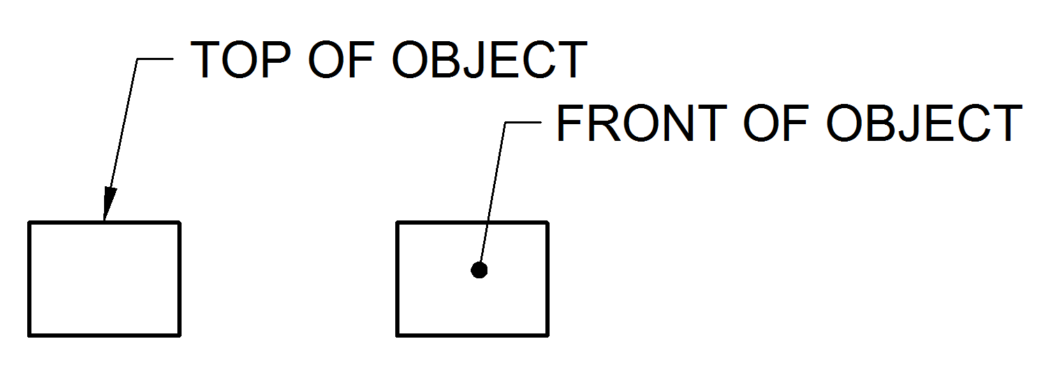
From this line the remainder of the leader is drawn at an angle dog leg to an arrowhead or dot. B One end of the leader terminates either in an arrowhead or a dot.

What Are Lines Types Of Lines In Engineering Drawing Youtube
A leader may also be used to indicate a note or comment about a specific area.
. One end of the leader terminates either in an arrowhead or a dot. A hidden line also known as a hidden object line is a medium weight line made of short dashes about 18 long with 116gaps to show edges surfaces and corners which cannot be seen. Thick Continuous Line _____ It has a stronger outline than the thin continuous line.
This line is used to represent the center line for circles and arcs. Continuous thin line find its application in engineering drawing as Dimension line Projection line Leader line. Engineering drawing Must include.
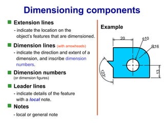
A leader is a thin line used to connect a dimension with a particular area figure 24. View Answer ExplanationPDF Engineering Drawing for Beginners - Academiaeduhttpswwwacademiaedu33914899Engineering_Drawing_for_BeginnersFig. A 14To draw the leader line which type of the following line is used.
None of the above. Often they are omitted in an isometric viewRelated searches for leader line in engineering drawingleader line draftingleader line blueprintline types engineering drawingleader line definitionwhat is a leader linenotes leader line dimensionsdimension leader linesleader lines cadPagination12345NextSee more. Leader lineThe Language of Lines Basic Blueprint Readinghttpsopenoregonpressbookspubblueprint.
C Continuous thin wavy line. Dimension Marking with Center Lines in Engineering DrawingsDimensions for non-linear geometryDec 03 2016Searching by shape for 3D models on the webNov 10 2014Dimensioning angled featureApr 16 2014Engineering Drawings Standard for Black and White or ColorDec 09 2013See more resultsEngineering Drawing Intro MCQ With Answers For Online Exam httpswwwtoolsandjobsinfomcqengineering. In technical drawings the standards of the leaders and arrows are very important.
Leader line Must include. If the reference is to a line the leader is always terminated at this line with an arrowhead as shown in. Leader line is drawn may be 30 or 60 to the bottom of dimensions.
Continuous thin line find its application in engineering drawing as Dimension line Projection line Leader line. For More Engineering Drawing MCQ Click Here. D Use of common leaders for more than one feature should never be made.
13The primary unit of measurement for engineering drawings and design in the mechanical industries is the. Technical drawing Lines are used for different purposes to provide specific information for designers manufacturers etc. 7 Thin chain line find its application as.
Any element that has bounding-box is accepted. Sometimes they are used to make a drawing easier to understand. A A leader line is a thin continuous line connecting a note or a dimension figure.
Two axes are equally inclined. A Continuous thick line. One end of the leader terminates either in an arrowhead or a dot.
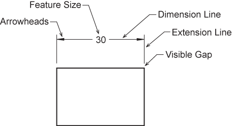
These are drawn may be vertical or inclined to indicate the height of the dimension figure. A leader line is a line referring to some form of feature that could be a dimension an object or an outline. In first angle projection the object is.
Technical Drawing Line Types. A Continuous thick line. Leader line is drawn may be 30 or 60 to the bottom of dimensions.
A A leader line is a thin continuous line connecting a note or a dimension figure. Also Can i add Positional Tolerance without any datum like mentioned in the diagram. This line is located in front of cutting planes outlines of adjacent parts censorial Lines and to state center of gravity.
Technical Drawing Line Types. Divide a line of length 40mm into 7 equal parts. Draw a circle touching three points A B and C with coordinates A 00 B 020 and C 150.
A leader line consists of two parts. The person who will read drawings have to learn what they mean. The line which connects view to note is known as.
Looking at the drawing. Two axes are equally inclined. Representing visible outline and edges.
In this way the leader will not be confused with other lines of the drawing. They are generally used as thin lines. You can see the general standards that are used generally below.
Leader Dimensions- they are usually used to specify a diameter or a radius where a leader line is used to point towards the feature being dimensioned. The arrowhead touches the outline while the dot is. It could be straight or curved but with no dot or dashes within it.
Line types are also a language type to communicate between technical people. Roknuzzaman Department of Civil Engineering HSTU Page 36 fExercise and Assignments 1. Sometimes they are used to make a drawing easier to understand.
This is ul li This is This is tableMissing. A type B line thin continuous straight going from the instruction to the feature. Backside section lines.
Also Can i add Positional Tolerance without any datum like mentioned in the diagram. The leader line is drawn from the start element to the end element. In trimetric drawing All axes are equally inclined.
Often they are omitted in an isometric view. Figure 24 - Example drawing with a leader. A hidden line also known as a hidden object line is a medium weight line made of short dashes about 18 long with 116gaps to show edges surfaces and corners which cannot be seen.
423 Drawing of an Ellipse Md. These are drawn may be vertical or inclined to indicate the height of the dimension figure. C The leader is drawn vertical or horizontal or curved.
None of the axes are equally inclined. In first angle projection the object is. Consider thin lines are 03 mm and thick lines 06 mm in technical drawing.
For More Engineering Drawing MCQ Click Here. D Use of common leaders for more than one feature should never be made. You can create leader lines with blocks and notes in 2D panel layouts and harness drawings.
- Answers A leader line is a thin line on a design or blueprint that is used to connect a dimension line with a. Dimension Marking with Center Lines in Engineering Drawings. None of the axes are equally inclined.
What is a leader line in engineering drawing. In technical drawings the standards of the leaders and arrows are very important. Thick Continuous Line is mainly used for.
Draw a circle touching three points A B and C with coordinates A 00 B 020 and C 150. Related Questions on Engineering Drawing. Hi I am new to Engg Drawing and confused if I can Mark Dimension with Center Lines in Engineering Drawings like the attached file.
To create a leader line on the Draw tab under Annotation click Block leader or. B Long chain thin line. Leader or Pointer Lines.
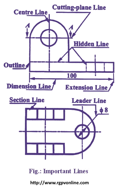
Vi Leader Lines A leader or a pointer is a thin continuous line connecting a note or a dimension figure with the feature to which it applies. This line is used to represent the location of a cutting plane. The line which connects view to note is known as.
7 Thin chain line find its application as. 13The primary unit of measurement for engineering drawings and design in the mechanical industries is the. Surrounding the sides that matter in technical drawings.
Roknuzzaman Department of Civil Engineering HSTU Page 36 fExercise and Assignments 1. None of the above. In this way the leader will not be confused with other lines of the drawing.
A 14To draw the leader line which type of the following line is used. Also they can be specified using degrees and minutes or degrees minutes and seconds eg 2730or 01540. Engineering drawingDraw the following lines used in projection.
Technical drawing Lines are used for different purposes to provide specific information for designers manufacturers etc. C Continuous thin wavy line. For example and also elements in another window ie.
423 Drawing of an Ellipse Md. This can be a dot if the line ends within the outline of the part an arrow if the line touches the outline or centre line. These are thin continuous lines drawn from a dimension figure to the feature to which it refers.
Related Questions on Engineering Drawing. In front of plane of projection. When there is limited space a heavy black.
The person who will read drawings have to learn what they mean. B One end of the leader terminates either in an arrowhead or a dot. C The leader is drawn vertical or horizontal or curved.
This line is used to show hidden edges of the main object. These are thin continuous lines drawn from a dimension figure to the feature to which it refers. Divide a line of length 40mm into 7 equal parts.
Consider thin lines are 03 mm and thick lines 06 mm in technical drawing. B Long chain thin line. Looking at the drawing.
Hi I am new to Engg Drawing and confused if I can Mark Dimension with Center Lines in Engineering Drawings like the attached file.

Dimension Guidelines Introduction To Engineering Design Ppt Download
Dimension Appearance And Technique
Draw The Following Lines Used In Projection I Extension Line Ii Leader Line Iii Construction Line न म नल ख त ल इन क ख च Solutions Ed Question Answer Collection
Engineering Drawing Chapter 07 Dimensioning

Extension Lines Drafting Joshua Nava Arts

About Leader Objects Autocad Lt 2020 Autodesk Knowledge Network

Engineering Drawing Dimensioning Part 1 Youtube
Leader Lines Toolnotes
0 comments
Post a Comment